Instructions for UNIGY Nitrogen Boosting Machine
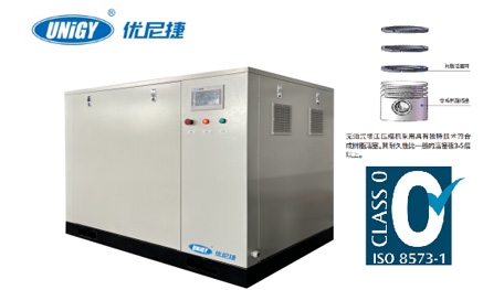
The UNIGY Nitrogen Booster is an oil-free gas boosting device developed and manufactured by UNIGY (Luoyang) Industrial Equipment Co., Ltd. It is widely used in industries such as lithium batteries, electronic welding, food packaging, chemical engineering, and power generation. Designed with the features of being "oil-free, quiet, efficient, and reliable," some models have obtained the TÜV Rheinland CLASS 0 oil-free certification.
Since UNIGY does not provide a downloadable PDF of the complete manual on its official website or public channels, the following content has been compiled based on publicly available technical data, product nameplate information, industry standards, and user feedback. It applies to typical models such as the OF60 and OF90-350-6-DP, and is intended for reference by engineering and technical personnel.
1. Working Principle
The UNIGY nitrogen booster operates on the principle of pneumatic liquid/gas-driven gas boosting. It uses low-pressure drive gas (typically compressed air) to push a piston in a reciprocating motion, thereby compressing the target medium (nitrogen) in a single or multi-stage process. The core structure includes:
Drive Chamber (Pneumatic section)
Boosting Chamber (Gas section)
Check Valve Assembly (Inlet/Outlet valves)
Directional Control Valve (Controls piston reciprocation)
Cooling and Buffering System (On some high-power models)
Throughout the entire process, the boosted gas has no contact with lubricating oil, ensuring the output nitrogen purity meets the CLASS 0 oil-free standard.
2. Typical Technical Specifications (Example: OF90-350-6-DP)
ItemParameter
Drive Gas Supply Pressure0.5 – 0.8 MPa (Dry, clean compressed air)
Gas to be BoostedNitrogen (N₂), Inlet pressure ≥ 0.1 MPa
Maximum Output Pressure35 MPa (350 bar)
Boosting Ratio6:1 (e.g., 0.6 MPa drive pressure yields approx. 3.6 MPa; actual pressure may be higher due to multi-stage cycling)
Output Flow (Theoretical)Approx. 90 L/min (Varies with drive pressure and back pressure)
Construction TypeW-type, double-acting, completely oil-free piston structure
MaterialsPiston: Heat-resistant synthetic resin; Cylinder: High-strength alloy steel; Seals: PTFE composite material
Noise Level≤ 75 dB(A)
WeightApprox. 120 kg (Varies by model)
Note: Actual Output Pressure = Drive Gas Pressure × Boosting Ratio × Efficiency Coefficient (typically 0.9 – 0.95)
3. Installation and Connection Requirements
Installation Environment
Install indoors in a well-ventilated area with an ambient temperature of 0 – 45°C.
Ensure the floor is level and sturdy to prevent vibration transmission.
Keep away from flammable, explosive, and corrosive gases.
Gas Supply Preparation
The drive gas source must pass through a three-stage filter (precision ≤ 0.01 μm, dew point ≤ -20°C).
It is recommended to install a pressure reducing valve and a water/oil separator to ensure the gas source is clean and dry.
Piping Connections
It is recommended to install a shut-off valve and pressure gauge at the nitrogen inlet.
A high-pressure check valve and a safety relief valve (set value ≤ maximum working pressure of the equipment) must be installed at the outlet.
All high-pressure joints should use taper threads (e.g., G1/4, NPT) or compression fittings. Do not use PTFE tape (plumber's tape); metal sealing gaskets are recommended.
4. Operating Procedures
Pre-Start Check
Confirm all piping connections are tight.
Check that the drive gas source pressure is within the 0.5 – 0.8 MPa range.
Close the outlet valve and open the inlet valve.
Start-Up and Operation
Slowly open the drive gas source; the unit will begin automatic reciprocating boosting.
Monitor the outlet pressure gauge. Once the set pressure is reached, the gas can be connected to the application equipment.
After a long downtime, it is recommended to run the unit unloaded for 2–3 minutes during the first start.
Shutdown Procedure
First, close the drive gas source.
Open the relief valve to release residual high pressure.
Close the nitrogen inlet valve.
5. Maintenance
Daily Maintenance: Check weekly for leaks at joints and clean the air inlet filter.
Regular Maintenance: After every 2000 hours of operation or 6 months, inspect the piston seals for wear.
Replacement Cycle: PTFE sealing rings have a lifespan of approximately 5000–8000 hours (depending on operating conditions).
Prohibited Actions: Do not use with oxygen or other oxidizing gases; do not operate above the rated pressure; do not run continuously at full load without cooling.
6. Safety Precautions
As this equipment is related to pressure vessels, operators must be trained.
Never disassemble fittings on the high-pressure side while under pressure.
It is recommended to integrate pressure sensors and automatic cut-off devices into the system.
If abnormal noise, overheating, or leakage occurs, stop the machine immediately for troubleshooting.
Document Acquisition Notice
To obtain the official version of the "UNIGY Nitrogen Booster User Manual" (including electrical diagrams, explosion drawings, and spare parts lists), please contact UNIGY's official sales department or authorized service providers (such as Nanjing Hante Trading Co., Ltd., Zhengzhou UNIGY Sales Company, etc.). Provide the model number and serial number from the equipment nameplate to receive the corresponding technical documentation.